Wednesday, November 11, 2015

Tiny FM band-stop filter

I've known for a while that I will need some kind of FM filtering.  I figured I could use the same SMA housing for a passive band-stop filter.  The main requirement is that it must pass the DC voltage to power the TinyLNA.  That includes no inductors connected to ground and preferably no resistors which will only consume power.

After reading this post, I figure I would use the same approach.  A simple 3rd order filter, but with slightly different design parameters.  I used 98MHz center frequency and wanted the edges to be -6dB.  This will probably not be enough, but I didn't want to put so much filtering on it that I lose the nearby air-traffic band just above that.


I plan on receiving several of these filters, so it will be relatively easy to adjust them.  I may consider assembling a test rig so I don't have to solder these into a connector to test them out.  Or perhaps I will just make a larger sized board that I can solder individual SMA connectors on either end.

I put together a simple schematic with some extra components just in case:

And then copied over most of the layout of the TinyLNA like board outline, copper pours, solder mask around the outside, etc.


This came together pretty quickly since I had all of the design files from the TinyLNA.  Considering the cost will be the same (80 cents for 3 boards), I figure I can go ahead and order some.  Even if they are a disaster, it's trivial to fix.

Housing evaluation

I've gotten in the SMA housing, and I wanted to check I calculated the size of the board correctly.  I cut up sticky-notes to approximate the board size.


I used digital calipers to verify I cut correctly.  It was slightly larger than what I designed which is ok to include margin of error.  The thickness is especially important.  Turns out it was just right.


You can see below how the board will fit inside the housing.  It will be tilted slightly so the center of the board touches the center post of the housing.  It leans over so one side of the board is resting of the bottom of the housing.  This will give me just enough room to get a soldering iron in there.


The housing slides over the top of the connector rather loose.  It does not lock in on the connector anywhere though so it will slide right off.   Looking at the datasheet, they have a cavity where you are supposed to use a punch on the housing.  Perhaps if I only punch it a little bit, I can slide the housing off when needed, but will hold enough when I want it to stay on.  It does not make contact with the mock PCB which is the real requirement.  I expect the boards will fit when they arrive.


Antenna brainstorming

I've ordered the parts for the TinyLNA board including the PCB.  In the meantime, I will begin constructing a Planar Disk Antenna as is suggested on the Reddit rtl-sdr forum.  I've acquired my 12 inch pizza pans from the dollar store, but considering my success with the whip antenna, I'm not sure how much better the performance will be.  I can only build it and find out.

In the photo above, there's a run of cable across the bottom pizza pan to a connector.  My plan is to solder a female SMA connector between the two pizza pans and then I will have the option of connecting the TinyLNA to it before the cable run back to the RTL-SDR.


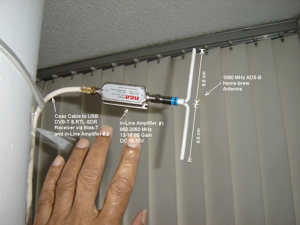
However, it may be far simpler to construct a small ADS-B dipole antenna. That would require just two stiff pieces of wire and the female SMA.  It wouldn't be that sturdy, but I may be able to use hot glue or something around the connector to provide some strain relief on the solder joints.  The instructions on this forum thread seems like a good guide to follow.


Whip antenna

Regarding the whip antenna, I've read horror stories about it not working or arriving broken and in general its low quality.  I perhaps got lucky because mine worked well.  I first checked continuity between the center post of the SMA and the whip to make sure there were no broken wires inside.  Next I removed the sticker on the bottom of the antenna.  It was a mistake to put one on there just for aesthetics.  Then I verified continuity between the bottom metal and magnet with the housing of the SMA.

I then had to go through my wife's cookie sheets and pie pans to find one that was both A) ferrous enough to have the magnet hold on and B) low resistance.  If it was high resistance across the sheet, then it would make a poor ground connection.  Ultimately none of the ones I had available were both, so I used one with good low resistance and risked the antenna falling over.

I found the magnet was too far recessed into the housing to make contact with the cookie sheet, so I just put a paper clip under it to bridge the gap.  Then I checked continuity between the cookie sheet and the housing of the SMA and it worked!

I was able to received good FM stations and voice air-traffic on my first attempt with SDR#.  I then started RTL1090 to check ADS-B reception and was able to receive data from aircraft over 100 miles away without obstructions.  This is from about 4 feet off the ground.  However, in the opposite direction where I do have obstructions, I only get maybe 30 miles or so.  That was much more than I expected given the negative stories about this antenna.

TinyLNA layout

Now that I've completed the schematic, I've transferred over to the PCB layout tool.  It's a tight fit, but there should be no problems.  It's not the best RF design, but I think the small size will forgive many of the problems.  I've used 50 ohm impedance traces as best as I could.  My only concern is the amount of DC power going through the inductors.  Those are some small inductors so I'm worried the MMIC will draw too much power.  The datasheet says 80mA max, but I will build the board and measure it.  The inductors saturate at 100mA, so I should be ok.  The image below is without the top and bottom copper pours turned on.  This is certainly going to test my soldering skills.


Since the board is so small, I've decided to use OSH Park for the fabrication.  They charge by board size, which is perfect for this board.  They've quoted me 80 cents for three boards (that's $0.80).  How can you beat that?  I'll just have to wait a couple of weeks for them to get here.  I chose to have exposed metal around the edges so I have lots of soldering options for my ground.  Normally I would space the ground away from the board edge, but I think that may be my only option for soldering ground.

TinyLNA Schematic

Next step was to get to fitting the components onto the board outline ASAP to see if I can make it fit.  For that I need a relatively complete schematic.  I can assume 0402 package sizes for passives.  And I want a provision for ESD protection because I'd rather have slightly degraded performance than risk a burnt out MMIC.

I also want a provision to send the DC voltage upstream, but I can't have both that and the ESD protection on the same board.  Since my overall goal is to make a white noise source, I'd like to use that DC power in the generator.  One big concern of mine is oscillation since there is now a positive feedback path from the output of the MMIC back to its input.  I figure I'll just have to test this to see if there's a problem.


Also, I don't mind if other people want to use this same design, so I plan on publishing all the design details here.  I'm not in this for the money or to build a business.  I have a pretty good day job.

TinyLNA part selection

After checking the datasheets, offsetting the board from the center will allow for roughly a 11.9mm x 8.4mm PCB assuming the standard 1.6mm thickness.  I'd like the standard thickness because it's cheaper.

Next it's choosing components.  Using guidance from the LNA4ALL design, I'd like to choose an MMIC which is cheaper and available at Digikey but also has the same package.  I settled on the SPF5043Z from RFMD.


I think it's possible to feed the DC voltage from the USB power right into the output of the MMIC, but I'm not sure how stable that voltage is.  So I'm going to add a provision for a voltage regulator.  It needs to be small, quiet, but able to deliver about 100mA and not generate much heat (since it's small it can't dissipate much).  Which means a linear regulator which is just below the expected input voltage.  I chose the LDK220C40R from ST Micro which outputs 4V.  There's a wide range of other voltages available in the same package/pinout so I can tweak it later if needed.


TinyLNA housing selection

I figure the next step is to make new antennas to improve my reception.  However, I have a problem in that I'd would like to characterize the antennas so I know that I've made them correctly.  I have no equipment to do this, so I am planning on making my own using guidance from one specific post on the RTL-SDR webpage.  I need a white noise source.  I would also like to have an LNA to boost the signal from the antennas I make.  I think I can kill two birds with one stone.

Most white noise sources I've seen are a rather simple source with one or two LNA stages.  So making my own LNA could go right into the white noise source.  So step one is to get an LNA.  I've reviewed a couple and it seems the LNA4ALL is very popular.  It's a good solution for $20.  However, it really needs to have the case which adds a significant cost ($60).  So I've decided to design my own customized LNA based on the LNA4ALL.


I've found a housing that I believe will work well.  It's about $8 which is way lower than $60.  However, this would mean I would have to feed DC power up the line.  But the RTL-SDR has a provision for that with a build-in bias-T.  I can solder a jumper to the RTL-SDR to get ~4.5V DC up the wire.

I believe I can fit a circuit board inside this housing with an LNA on it.  For sure it will be a tight fit to get a PCB in there with everything I need but I believe it can be done.  The shield will slide over the top of it providing a good ground and EMI/ESD protection.  Next step is to figure out how much space I actually have to cram circuits in there.


Introduction

I've created this blog to track my design efforts in the area of RF electronics.  This is a new field to me, so I'm learning as I go.  However, I've had quite a bit of experience in digital and analog circuit design including high-frequency digital.  So I'm familiar with topics such as transmission lines and impedance matching.

My focus is on low-cost but trying to maximize performance.  I recently received my first RF component - the RTL-SDR dongle.  It's difficult for me to compare performance to other receivers, but it seems to work well for me out of the box with SDR# using the guidance provided on their website.

I haven't been publishing my blogs yet, but I think I will publish them all at once now.